|
Introduction to The World's Straightest Commando This endeavor is another step in the continuing process of improving and determining the black art of motorcycle handling. Decades of expert observation, trial, error and consensus opinion have produced conclusions that appear obvious but are deceptively difficult to achieve. Statistics; dynamics; geometry; materials; fabrication and evaluation techniques each deserve long, full explanations, the space for which is not available here. The subject allows very little room for ignorance or lowered standards. Cascading tolerances quickly deteriorate the product if one is not exacting. Genuine knowledge of what is acceptable comes only from a vast amount of repetitive execution and evaluation. There are good-handling motorcycles with varying specifications of distance, angle, mass, and force. All, however, have common features: First, supple pieces should be definitively supple. The definition of this suppleness is indeed subjective but only within limits. Stiff pieces should be very stiff. Second, The swing arm pivot axis should be perpendicular to the steering axis in the frontal and vertical views. The wheels should be directly in line with each other and with the steering axis. The Commando has an isolastic system which should be supple in the vertical plane to a degree that suits one's orthopedic and nervous systems, but stiff in all others. One may be able to improve things slightly with careful measurements and adjustments, but if any of these aspects are built in badly, one must unbuild and rebuild them properly. Laser frame jigs are tools to locate errors, but someone with a press, torch or mill will be required to correct them. A Helium-Neon laser projects a red beam that resembles the mark that a red magic marker makes on white felt. It's pretty, looks high tech and can be seen easily. The problem is that the edge is fuzzy and extremely difficult to define exactly. If a frame is bent, to get it straight one can do no better than the degree of exactitude with which one begins. Once you elect to go beyond bending the frame "close", which very likely may end up distorting it somewhere else, the frame can be cut, jigged and otherwise prepared for the repair. When welded, heat causes metal to expand; cooling causes it to shrink and distortions occur. It is best to do the highly stressful welding and heat treating first, and machine any holes afterwards. Bear in mind, one's own Commando may have more problems than Stevan's. For instance, his rear frame loop wasn't bent, the center stand hadn't sagged and the side stand wasn't bent or torn away. He wasn't directly aware of most of the misalignments. What began as a rear wheel bearing replacement ended after several months of work resulting as a blueprinted, restored, straight Commando. Enjoy his tale. The World's Straightest Commando
I was never satisfied with the handling of my Commando. When I checked the alignment using strings and straight-edges, the wheels appeared to be nearly aligned, but I was certain that they were not. The front tire was unevenly worn, and the rear wheel was not centered in the rear fender loop. My motorcycle has a Barnes-type rear wheel with multiple axle spacers and may never have been properly centered. The greater question was, exactly where was the wheel in relation to the steering head, and was it ever right? This is a serious question on any stock Commando. Since the entire motor package is suspended, there are multiple variables that can affect this important relationship. Given these variables, I am certain that the rear wheel on most Commandos is not even close to being in proper relationship to the steering head. The most critical factors (under our control) that affect the handling of our machines are: complete and unyielding perpendicularity of the steering head to the swing arm in two axes; and keeping both wheels and the arc of the rear wheel travel, in line with each other and the steering head. There is more to this than you might think. On most motorcycles these relationships are fixed at the time of manufacture and are either within allowable tolerances or not. Bear in mind, however, that "within tolerance" may be far from perfect. The Commando frame system is unique in that there is a large degree of alignment adjustability inherent in the design in addition to what is misaligned yet within tolerance. This means that, in addition to what wasn't straight from the factory, it can easily be re-assembled so it's even worse. However, if you know what to look for, it can also be re-assembled so that the alignment is improved.
I had no idea of the extent of what I was getting into when I started this project, but I can now say that the result of the Level Three Alignment is well worth the effort. Were I ever to own another Commando, I would do every bit of the Level Three Alignment on it. There is always more than one way to do anything, but I don't think you can go wrong following these suggestions. If you have anything to add, I'd love to hear from you. Meanwhile, I have what I believe is the straightest Commando in the world. The Problem Exists When I used strings and then straight edges to check my wheel alignment, it looked like the wheels were somewhere within 1/4" of being in-line. I still wasn't positive that the steering head and front wheel were straight in relation to the center line of the frame, and the rear wheel seemed off-center in relation to the rear fender loop. I've been told repeatedly, "don't look at the fender loop, you can't go by that". This must be because so many Commandos have the rear wheel offset to the left in the fender loop that it is now considered normal. I could never believe that any factory would build a frame that was straight but appeared to be this far out. The one thing I was sure of on my machine was that the rear wheel axle was straight in the swing arm and the wheel wasn't cocked. I know this because there are accurate wheel alignment marks on the swing arm ends. Whether or not the wheel was on the center line of the motorcycle was still an open question. The frame backbone certainly looked straight in relation to the steering head, and the rear fender loop looked right in relation to the backbone. Something was amiss! Finding the Problem I have the good fortune of knowing Ken Augustine of Kinetic Analysis in San Rafael, California. His work on cylinder heads and motors is legendary. This frame blueprint developed as an extension from his idea of blueprinting the cradle. I had gone to Ken's shop simply to change my rear wheel bearings, but found I had to do extensive hub repair to save the wheel. I wanted to make sure that the wheel was in alignment when I reassembled it, and it was during this process that I realized that there was no fixed reference point from which to measure.
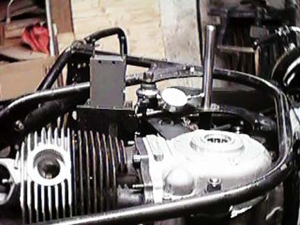
How Much Misalignment Can Be Tolerated? Ken often corrects frame misalignments on racing motorcycles that come to him when riders encounter scary handling problems. He told me about one motorcycle-a new, uncrashed 600 cc production sport bike--that had a severe high-speed wobble and extreme, asymmetrical rear tire wear. The rider was wearing out a set of handlebar grips and footpeg rubbers per race and was wobbling so badly on the straights that nobody would pass him. It turned out that the swing arm pivot was out of square with the steering head by a mere .029". This illustrates the dramatic effect that out-of-squareness between the steering head and swing arm pivot can have. It also illustrates that not even racers bother to check frame alignment unless they can feel there is a big problem. Ken's idea is that if a motorcycle frame isn't right, bending it may get it close, but the only way to get the critical relationship between the steering head and the swing arm pivot right is to measure everything, determine the error, and then re-machine as necessary to correct things. He has learned that taking the easier route of "getting things close" usually means you get to do it over again anyway. My own background includes designing and constructing bicycle racing frames and aligning them to within several thousandths of an inch, as well as building bicycle wheels to similar tolerances. The idea of checking frames for alignment and making corrections makes perfect sense to me, because I haven't seen a bicycle frame yet that did not require some adjustment, no matter how skilled the fabricator. Welded assemblies, including motorcycle frames, always distort when subjected to the heat of brazing or welding, no matter how firmly the assembly is jigged. Understanding the Norton Isolastic System The Norton isolastic system used on the Commando has a couple of inherent problems. One has to do with the manufacturing method used at Norton, and the other is a result of managerial penny-pinching. Did you know that the Mark III-type adjustable isolastics were originally used on the prototype models, but were dropped from the production version because shimmed washers were cheaper? Problem number one is that the front and rear tubes holding the isolastic rubbers were straight, with the end faces machined parallel to each other and square to their bores, before they were welded to their respective side plates. Once welded, they distort. Unless they have been corrected, the end faces of every isolastic mounting tube are out of square and out of parallel. This presents a problem when you try to adjust your PTFE washers. It is obvious that you will get the best adjustment and the longest wear from the washers if everything is properly lubricated and exactly square (as the designers intended). With the assembly out of square, you can only adjust properly to the widest part of each assembly. This gives only one small area of contact with the desired clearance, leaves the rest of the joint with too much clearance and allows angular displacement (rocking). The unit loading (total force divided by surface area) exceeds the material strength of the PTFE washers and immediate wear ensues. This allows the handling to deteriorate. The second problem is easily solved with an after-market part. Once you understand the design necessity, you should run, not walk, to the phone and order one from your dealer! This analysis of the isolastic system has two basic parts: 1) The isolastic concept is based on the mathematical idea that three points determine a plane; 2) The "moment" about any point (torque) is proportional to the distance between the forces. Wider spacing yields more resistance to the upsetting torque (side force). In general, the front and rear isolastic mounts form the first two out of three points that determine the plane of the engine-gearbox-rear wheel unit. The upper motor mount is the third point defining this plane, but the stock mount is not adequate for this purpose because it compresses and allows the plane to rotate. When it flexes, it defaults its load bearing capacity down to the tops of the front and rear isolastics. This reduces the effective load bearing height of the triangle to about two inches (the diameter of the PTFE washer), which has to resist the input torque generated by the weight of the machine and rider, as well as the cornering forces leveraged in by the radius of the rear wheel assembly. Specifically, the exhaust system rubber mounts compress and allow the top of the motor unit to move sideways. This motion is across the axis of the wheel plane, which allows the suspended unit to deflect, causing the PTFE washers to wear unevenly and prematurely. The effect is more pronounced at the rear washers, but is a factor at the front ones as well. The end result is that the rear wheel deflects out-of-plane with the front wheel, which is not desirable for good handling. Cornering forces, along with the leverage that the rear wheel has on that top mount, are considerably more than you might imagine. In fact, in this situation you can look at the stock isolastic mounts as being a fulcrum, the rear wheel as a lever to the fulcrum, and the top mount as the only limiting resistance to motion at the fulcrum. It would appear that whoever decided to use the exhaust system rubbers as the top motor-unit mount may have looked at the input lever (distance from the rear tire contact patch to the rear isolastic) as being roughly equal to the output lever (distance from the rear isolastic to the top motor mount) and decided that compressible rubber would be adequate to control side movement. The rubbers do compress, and this makes the stock isolastic mounts the fulcrum of a teeter-totter, with one end in (limited) motion and with a lot of force coming in at the other. Your PTFE washers are in the middle, and bear the brunt of this. They were never designed to take this much pressure, which is evidenced by the way they wear: they all wear more at the outer edge because the outer edge gets loaded beyond its material strength. The greater the clearance (and wear) at the PTFE washers, the more accelerated further wear becomes. In a blueprinted system with an isolastic head steady, the washers will wear much more evenly because rocking during cornering is eliminated. Why an Isolastic Head Steady is Necessary The 750 style of head steady flexed severely and cracked in service and was replaced by the box section 850 type. This was an improvement, but it still had the compressible rubber mounts. The INOA Tech Digest suggests that when you have your standard head steady off the machine, you should shake the bike sideways and pay attention to how much the motor moves. This is an excellent illustration of how critical the upper mount is in controlling this motion and inadvertently infers that what you really need is an isolastic head steady. The only proper way to prevent this motion at the upper mount is to install a Norvil-type (isolastic) head-steady because they do not compress sideways and they work exactly the same way as the other two isolastic mounts in only allowing motion in the direction that is expected. Three isolastic mounting points determine a plane and, in this case, complete the triangulation of the power unit in the frame. I don't know if an isolastic head steady was ever specified by the original designer. I suspect it was, because once you understand the nature and physics of the system, you realize it's absolutely necessary. It seems incomprehensible that Norton did not install one as standard equipment. It is now up to you, the owner to do this. It must be correctly installed and there is also more to this than you might think. Preliminary Frame Work After completely stripping my machine to the bare frame, Ken did some detail welding that included a box section reinforcement to support the rear fender loop an extra seven (unobtrusive) inches behind the shock absorber mount. This is a new type of reinforcement that does not interfere with, or require any modification to, the shock absorber top collars. We did this because the rear loop is not adequately supported and bends readily when you carry a heavy passenger or luggage. It is a worthwhile modification on any Commando frame, particularly the Interstate model. Checking the Main Frame The next step was to check the accuracy of the location of the main isolastic mounts in relation to the steering head. A tool-steel rod was fitted through the steering head bearings and supported by precision blocks on the granite table. First, the frame was blocked up at the rear with an adjustable mount and the main backbone tube was checked for height, front and rear, from the table using a Vernier height gauge. We adjusted the frame so that the backbone was parallel to the table, plus or minus .002". Second, we calculated the height of the steering head center from the granite table. Third, we measured the distance between the two rear iso mounting plates and added half of this to the height of the steering head center. We used this combined figure as the height from the table to the inner face of the upper rear mounting plate. This is more accurate than working off just the frame back bone. Tool-steel rods were placed into each of the two pairs of iso mounting plates that are welded to the frame cradle. The rods were measured for perpendicularity with a dial indicator held by a vertical sliding column with an air bearing for the slide. Two measurements were taken along the lengths of the rods at 90� to each other. The results were disappointing: on the right side of the frame, the rear mounting hole needed to be moved .032" to the rear and down .014". The front hole needed to be moved .043" to the front and down .038". The Problem With Production Tolerances If my frame is typical of production tolerances, the fore and aft discrepancy will keep the isos out of parallel planes and the vertical discrepancy will keep the rear wheel out of plane with the steering head. Even if your wheels appear to align, the paths they travel through don't. Adding to this all the other things that may be out of alignment and/or adjustment on a 20-year-old motorcycle, it's easy to see why most Commandos have a weaving feel when going in a straight line and don't have the high speed stability of a Featherbed. The Frame Fix The two holes on the left side of the frame were partially welded, and the entire set-up was transferred to a milling machine, where the holes were re-cut exactly opposite their counterparts. Squaring the Cradle and Other Motor Mounts The next task was to square the faces of the isolastic tubes on the cradle, front mount and head steady. The Mk 3-type front mount is welded completely around the circumference of the tube, and so is more symmetrically distorted than the earlier type, but still needs some trimming. The rear tube is welded to the cradle side plates on only about 1/3 of its circumference and is quite measurably warped. Norvil-type top isos are similarly warped, with the addition of being egg shaped due to the thin wall thickness of the tubing. It is necessary to have the end faces of all three tubes cut square to their axes. Straightening the Swing Arm The next part onto the granite table was the swing arm. The axle slot was filed so the axle was within .002" of parallel to the swing arm spindle, and the legs were checked to make sure the axle and the spindle were exactly parallel. Something you may want to do while the swing arm is off the bike is put some accurate wheel alignment marks on your fork ends. You can use a beam compass (or measure carefully) with one end set on an edge of the fitted spindle and scribe a mark on the fork end where it will be visible with the chain adjusters. Without changing dimensions, mark the opposite side as well. Repeat this in 1/8" increments along the length of useable fork end on both sides and make permanent punch marks. You will never again have to wonder if the wheel is straight when you adjust the final drive chain. The Forks The last assemblies to go on the granite were the front fork stanchions and yokes. You can roll the stanchions to make sure they are straight. If they have seen much service, you will notice that the one on the side that carries the brake caliper is probably bent. It must be straightened or replaced. It is also necessary to individually bend each yoke so that both stanchions are parallel to each other and to the stem. Assembling and drawing misaligned yokes and bent stanchions together in the hope of self-alignment is a doomed endeavor. The forks will not function well unless everything is parallel, and the only way they will be parallel is if you check them and correct all misalignments. Fitting the Main Motor Mounts While inspecting my engine mounting tube caps (part #s 060684 and 060685), I noticed that they showed some signs of wear, so Ken resurfaced them on his precision grinder. The next step required some partial assembly: I installed Mk 3 adjustable isolastics, mounted the cradle in the frame with zero clearance for the PTFE washers, mounted an empty set of crankcases, installed the front mount (again with zero clearance), tightened both mounts, and fitted a tool steel rod into the swing arm spindle hole. The frame went back on the granite table so I could measure the tool steel rod in the spindle hole with the vertical dial indicator to make sure the spindle was squarely aligned. I was very surprised when it wasn't. After some head-scratching, I removed the adjustable and fixed collars along with the PTFE washers from the front motor mount, leaving just the caps on the iso tube, and reinserted the front iso bolt, tightening only the rear bolt. I then measured the space on each side, between the cap and the frame mounting tab (again with the rear set for zero clearance). When I measured the collars with their respective PTFE washers, I found that the parts for the left side were .040" larger than their space in the frame, and the parts for the right side were .040" smaller than their space. After grinding .040" from the left side and adding a .040" washer to the right side, I set the frame assembly up on the granite table once again to check it. This time, the tool steel rod in the spindle hole measured perfectly square. The primary relationship between the swing arm pivot and the steering head had finally been established as absolutely correct. Fitting the Swing Arm and Bushings to the Cradle While I was having my cradle blueprinted, I found some further fitting necessary for the swing arm bushings. There is some side play between the swing arm bushings and the cradle that most owners don't know of or think about. I figured I had side play when, some months ago, the little threaded rod (that connects the oil reservoir end caps) broke and I lost the right side end cap. If the rod was stationary, there was no reason for it to break. Since it broke, it seemed it was likely flexing and I looked for the cause. The cause was side clearance, which is also one of the factors that give Commandos that weaving feel when they are going straight. It is masked from the casual assembler by the compression of the oil reservoir seals. Of course, worn-out bushings, spindle and spindle bore, the inadequate stock head steady, and sloppy, non-parallel isolastics with excessive clearance all contribute to this weave and need to be fixed. Before you can correct side clearance, you have to measure it. To get an accurate measurement, you have to make the load-bearing surfaces flat. I measured the area on the cradle against which the bushing bears with a large micrometer. I found that the wear was not even along the face: the edge closest to the spindle hole was proud, and the outer circumference of the bushing wear area was worn down .005" all the way around. I also found that the cradle plates were sucked in a bit from when I had spindle pinch bolts welded on a couple of years ago. To correct the problem, Ken made these surfaces flat, perpendicular to the spindle bore. Once you have made the load-bearing surfaces flat and are ready to measure side clearance, assemble the swing arm, bushings and spindle to the cradle with something in the place of the oil reservoir seals that is the same thickness. I measured the thickness of the metal washer that is the base of the seal (I am using the Mk 3 type). I had some old ones that were the same thickness, so I scraped all the rubber off them, installed them as measuring washers with the bushings into the swing arm and mounted the swing arm to the cradle. When I measured with feeler gauges, I found that I had .035" side clearance, which is excessive. If you just assemble the stock parts, the seals will prevent you from being able to feel or measure the excess clearance. You must check it to know how much is there and shim as necessary to correct the fit. I found some shims in Ken's amazing inventory that fit between the bushing and the swing arm, and set my side clearance to .003". Rear iso shims will also fit if you enlarge the i.d. slightly. To keep the reservoir oil-tight, I found it necessary to radius the back edge of the cradle where the rubber swing arm seals are offered to the cradle. If this isn't done the back edge will cut the seals during assembly. It is also necessary to radius the edge of the spindle hole for the same reason. Remove your measuring washers and install the shims, new seals, and bushings into the swing arm. Grease the seals well, and wiggle the swing arm carefully onto the cradle. With such tight clearance, you have to be very careful--it is easy to ruin the new seals! Now, accurately mark the true center of the swing arm. Install the cradle/swing arm assembly in the frame with the PTFE washer clearance set to zero. Measure in from each side plate to determine where the center is, and mark the spot on the top of the swing arm. If your frame is not bent, this should be exactly on the center line of the motorcycle. Swing Arm Bushing Oil Reservoir After you instal the spindle end caps, the finishing touch for this assembly is to install a 1/4" x 28 t.p.i. allen screw with a hole drilled through the center, in place of the screw that fixes the spindle to the cradle. The screw needs a 1/8" (or thicker) spacer that is the same o.d. as the screw head. Put a piece of clear fuel line about 18" long onto the screw head and secure it with a hose clamp. If you don't have the spacer under the screw head, the tubing won't stay on. Trim the hose to a convenient length, cable-tie it to your frame, and you now have a place to fill the swing arm spindle oil reservoir so you can see if you have oil in it! NCNOC member Robert Newman came up with this idea and has kits available. The Rear Wheel At this point, you can check your rear wheel to make sure it is properly centered in the swing arm. Install the rear wheel so that it is straight in the swing arm and spin it to make sure it is true. If it is not, it must be trued at this time. Look to see if the center of the rim or tire is in line with the centerline mark you made on the swing arm. You can also measure the distance from the frame tube (adjacent to the iso mounting plate) to the rim. Note that the edge of the tire will be noticeably closer to the swing arm on the right side. This is normal. The swing arm is not symmetrical because the engine and cradle assembly is offset 1/4". If the wheel does not line up correctly, you will need to have the spokes adjusted to move the rim over. Don't do this yourself unless you know what you are doing. Fitting the Isolastic Head Steady When you get an isolastic head steady, you will notice that they don't come with instructions. I have never seen any information on how to properly install one. This method is the best one that I could figure out and should be undertaken after all the straightening work described above if you want the best results. It may also be better to get this part in regular steel, not stainless steel. The stainless alloy in the one that I got seemed a little soft, and stainless steel tends to distort more when welded. More importantly, the non-magnetic stainless steel can't easily be squared on a magnetic precision grinder. Before you proceed, you need to do two things to your top end pieces. Every Norton cylinder block that Ken has ever seen has the head gasket (top) surface out of square with the cylinder base by .0065". They are very consistent. Every single one is off by exactly the same amount. Fortunately, Norton registered the cylinder bores off the base flange, so the top surface can be safely made parallel to the base by grinding. If you have any doubts, check your bores to make sure they are straight in relation to the base flange first. On the head, the head gasket surface needs to be milled flat. The top surface of the rocker box has three flat spots, to which the head steady bolts, that need to be milled flat as well. The two surfaces also need to be parallel. This may not seem like much, but out-of-squareness is cumulative and all of these surfaces will have an effect on how well the top iso mounts. We installed the correctly-spaced complete front motor mount with empty crank cases in the frame. The front and rear isos were both set to zero clearance and tightened. I then mounted the cylinders, head gasket and head. I assembled the top iso, tightened the iso nuts and checked the clearance. You must have some measurable clearance to accomplish the next step. If there is none (like mine had when I got it), this should be solved when you square the sides, or you can add a small shim washer between the iso rubbers inside the tube. (If you use a shim washer, you can glue one side to one iso rubber center tube using silicone seal or some other suitable adhesive to keep it from falling out of place when you remove the bolt.). Once you have some clearance, measure it. Add to this measurement front iso shims (they should fit the top mount) of a thickness such that the combination will be the total amount of final clearance you want to have. For example, if you have .010" clearance before adding shims, and you want a total final clearance of .010", add a shim that is .005" to each side (.010" total) and tighten the assembly. This will leave .005" clearance per side when the shims are removed later.If you have squared the faces of all three iso mounts, .010" total final clearance will work. If you haven't squared everything, you may want .015" to .020". Now, mount the top iso unit to your head with the three allen screws. You may need to add spacers to make all four side plate mounting bolts line up (the two for the front saddle mount, over the small diameter horizontal tube, and the two for the threaded holes in the frame, for the stock head steady rubber mounts that you are no longer using) without having to lift the motor. I had to add about 1/8" to mine. You can make a spacer plate, or find three large-diameter washers a bit thicker than necessary and grind them. If you use washers or individual spacers, it is important that all three be exactly the same thickness to keep the mount square with the head. Having gotten the lower isos in exactly parallel planes, you are now fitting the top iso so that its two working surfaces are perfectly parallel to the other isos. With the extra shims for clearance in place, the space between the plates is determined by the width of the iso. The space between the plates and the frame determines how wide the saddle should be and what the dimensions of the spacers for the rear bolts should be. These parts need to be fitted exactly to the space defined by the side plates. It is extremely important to get this step right! If the saddle piece is too wide, trim it at this time. Install the (trimmed) saddle piece and put the rear bolts through the side plates into the threads in the frame without their spacers. Do not tighten them even slightly or your measurements won't be accurate. They are just there to hold the plates in position for some measurements. If you have clearance between the side of the saddle and the iso side plates, use feeler gauges and measure each side. Add a shim washer that is the thickness to give zero clearance. Use a micrometer or precision caliper to measure the washers. Put in the front (saddle) bolts and tighten them. Precisely measure the space between the side of the plate and the frame to determine the size of the rear spacers you will need. Measure the spacers that came with the iso head steady. If they are too long, trim each one so it is exactly the same size as the space it fits. If they are too short, put them in position with the bolts loose, to hold the spacers and measure the clearance with feeler gauges. Find a shim that is exactly the right thickness or, better yet, make some new spacers that are the right dimension. I recommend that you mark all of these pieces for position and engrave the thickness of any shims adjacent to where they are installed. This will save you from getting things mixed up when you or someone else removes the head. Engrave both saddle pieces so you know which faces front, and if the rear bolt spacers are not identical, mark them. Now remove the side plates, remove the iso shim(s) that you installed for clearance, lube the PTFE washers with silicone grease, reassemble the side plates to the frame and torque the two iso nuts to 25 ft. lbs. and your correctly fitted assembly is complete. If you are doing this to a running motorcycle, adjust your lower isos from zero to running clearance and you are done. The Bare Minimum Even if you aren't going to all the trouble of correcting the mounting holes and squaring up the faces of the mounts, checking the front pieces against the space they fit into while the rear is tightened down at zero clearance should be standard procedure for all Commando assembly. This is easier if you have adjustable isolastics in at least the rear cradle. An option exists for those of you who don't want to completely replace your shim-type isos. Mick Hemmings has a kit that was invented by an NOC member here in the U.S.A., that gives you Mk3-style adjustability using most of your stock pieces. If your rubbers are in good shape, this could be just what you need. Just remember when installing the isos into their mounting tubes to lubricate them liberally with silicone grease. I used Ace Hardware plumber's silicone grease, which should be easy to find almost anywhere. This is runny stuff and won't stay in place on the PTFE washers forever, so I also have a spray can of electrician's silicone spray that I use to re-lubricate them periodically. Even in a non-blueprinted frame, the rear motor mount is in roughly the center of the motorcycle and is the logical place from which to start the basic alignment process. If you set it to zero clearance and then set the front spacing using this procedure, you are likely to be more correct than if you just assemble stock parts without checking them. I must point out that although it is necessary to check the front spacing in this way, it is not a substitute for blueprinting the isolastic mounts and the mounting holes in the frame. It is a garage or workshop expediency that is necessary to get the front and rear isos closer to being parallel. If you don't do it, your isos will likely be further away from the goal, and your engine/rear wheel unit will more likely be askew of the centerline. Even though it is less than perfect, when you plan on installing an iso head steady, you must set up the front mount in this way if you want to have any chance at having all three isos in close-to-parallel planes. Why Bother? You may be wondering, "How much difference does .040" make on a front motor mount?" Do you know it's only .040"? If you don't check, you don't know. PTFE washers come in different thicknesses. If yours aren't identical, you may have only to reverse the washers to improve the alignment. If your only problem was a mere .040" (one millimeter) in one spot, it might not matter. However, having done all of this to my motorcycle, I can just about guarantee that everything that can be wrong on yours is indeed wrong, and really needs to be corrected. Ask yourself this: Does your bike do the "Commando head shake" at high speed? Remember that in the example of the 600 cc sport bike, the swing arm was out by a measly .029". It should be obvious that the number of places that a Commando can be wrong far exceeds those of the average motorcycle, and the errors are cumulative. Nortons are said to handle well, but a lot of this is due to the broad torque band and relative lack of power. Don't compare your handling to a 1971 Honda 750 Four or a 1980 Z1 Kawasaki; compare it to a 1997 Ducati SuperSport. If our Nortons made Ducati horsepower, we would have to pay far more attention to chassis and suspension set-up. As it is, most Commandos spend only a small fraction of time over 70 m.p.h. and those riders that do exceed this regularly will probably agree that there is ample room for improvement. End Result So, how much of this should you really do? If your bike is apart, you should definitely do as much of this as you can afford. If you bike is not apart, plan on it anyway. It makes a difference and it's worth doing. On the Northern California BSA Owners Club 1997 Eighth Annual Don Danmeier 50th Birthday Ride, I let several people ride my bike, including the fellow I bought it from almost 20 years ago. His first comment was, "It wasn't this nice when I sold it to you". His second was, "It tracks the straightest of any Commando I've ever ridden and feels more stable. It doesn't do the usual Commando 'snake weave'". He is now getting ready to blueprint a bike. The other riders were similarly impressed. There is a big difference between "Well, it runs" and "It runs well"! I recommend that at a minimum, a basic Level One Alignment should include these steps: fit Vernier isos, check the front spacing and install an iso head steady. Check to see if your rear wheel is properly spaced and centered in the frame. All of your clearances will be wider than optimum but this should be a significant improvement over standard assembly. Level Two Alignment should include all of this plus blueprinting all three isos. Straighten the swing arm, service and fit the swing arm bushings, mark the centerline of the swing arm and put alignment marks on the swing arm ends. Square the top face of the cylinders as well as the two surfaces on the head. Due to the probable misalignment of the main frame motor mounts, the only isos that will be in parallel planes will be the ones in the head steady. The cradle isos will be greatly improved but not yet perfect. Align the forks (optional for Level Two). If you've gone this far, it isn't much more trouble to do the Level Three Alignment and blueprint the main iso mounting holes in the frame and do the forks. The isolastic system is completely blueprinted and the isos are all in parallel planes. All the wear parts will last longer and you can run much tighter clearances, which further improves longevity. A major advantage of Vernier style adjusters is that you can set them on the tight side, and loosen them a little at a time until the vibration smooths out and goes away. This allows you to find the sweet spot for your particular machine, no matter which level alignment you are doing. You can also calculate how much clearance you have by how much you have turned the adjuster. One complete turn of the adjuster equals .050" clearance movement. If the adjuster is turned the distance between two of the eight holes, you will have clearance movement of .006". I am running between .006" to .010" total clearance on my lower isos (that's .003" to .005" each side) and vibration is completely acceptable. If you do any of this, you will be pleased. If you do all of this, you will be thrilled! To Reach Everyone Ken Augustine is no longer among us, headed toward bench racing in parts unknown. Kinetic Analysis was located at 53B Mark Drive, San Rafael, CA. Frames and cradle prep for this job should be delivered to your contractor clean, including scrubbing all the old rubber from the inside of the iso tubes. Include all of your iso pieces, mounting bolts, swing arm and bushings and spindle pieces. Robert Newman is deceased as well. Mick Hemmings is in England at 011 44 1604 38505. My phone number is (510) 910-6137. You can see my Norton on Phantom Oiler under "Son of P-11". You may notice an interesting detail: the entire exhaust system is mounted rigidly to the cradle and moves with the engine. But that's another story. . . copyright Stevan Thomas, 1998-2019 |
||
| Back to Phantom Oiler Table of Contents | ||
| Comments or suggestions? Drop us a note! Flames are OK if you can spel! | ||
| Email to: Phantom Oiler | ||
| Design: TC Enterprises copyright 1999-2019 | ||
 This
article describes how to improve both the frame alignment of a Norton
Commando and set up the isolastics. The goal of this process is
to have the alignment of the wheels and steering head in the same
plane, and the isolastic surfaces all in planes parallel to each
other and to the plane of the wheels. There are recommendations
for three different levels of alignment. Level One is the basic
minimum. Level Two requires cradle removal and some work on top
end motor pieces. Level Three includes completely blueprinting the
main frame and requires the machine to be thoroughly stripped. Once
you understand the alignment process, the breakdown into these three
categories will be self-evident.
This
article describes how to improve both the frame alignment of a Norton
Commando and set up the isolastics. The goal of this process is
to have the alignment of the wheels and steering head in the same
plane, and the isolastic surfaces all in planes parallel to each
other and to the plane of the wheels. There are recommendations
for three different levels of alignment. Level One is the basic
minimum. Level Two requires cradle removal and some work on top
end motor pieces. Level Three includes completely blueprinting the
main frame and requires the machine to be thoroughly stripped. Once
you understand the alignment process, the breakdown into these three
categories will be self-evident. 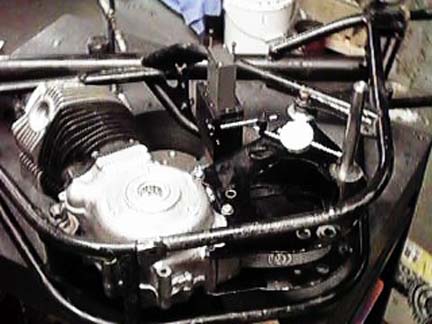 Ken
pointed out that this is a problem particularly with Commandos and
said the only solution was to take the bike apart and check everything.
Since Ken has a machinist's granite surface table and the instruments
for checking every aspect of frame alignment, and I had been planning
on doing the cradle sooner or later anyway, it looked like the time
had arrived.
Ken
pointed out that this is a problem particularly with Commandos and
said the only solution was to take the bike apart and check everything.
Since Ken has a machinist's granite surface table and the instruments
for checking every aspect of frame alignment, and I had been planning
on doing the cradle sooner or later anyway, it looked like the time
had arrived.